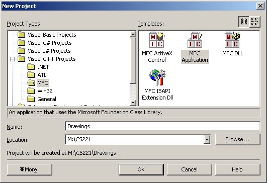
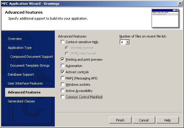
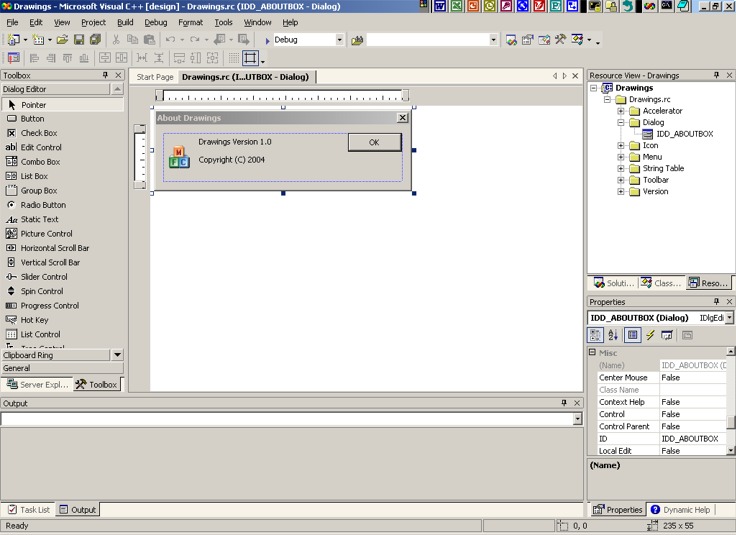
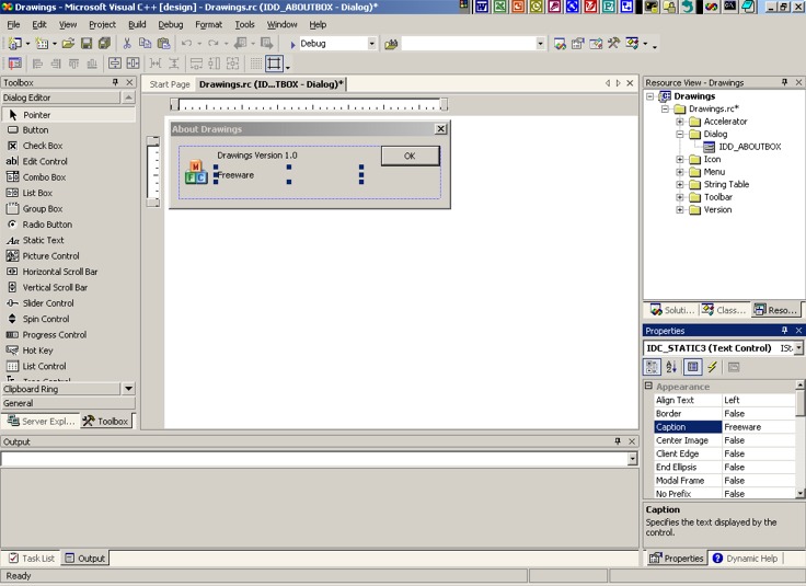
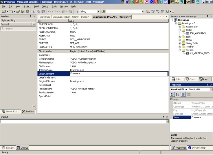
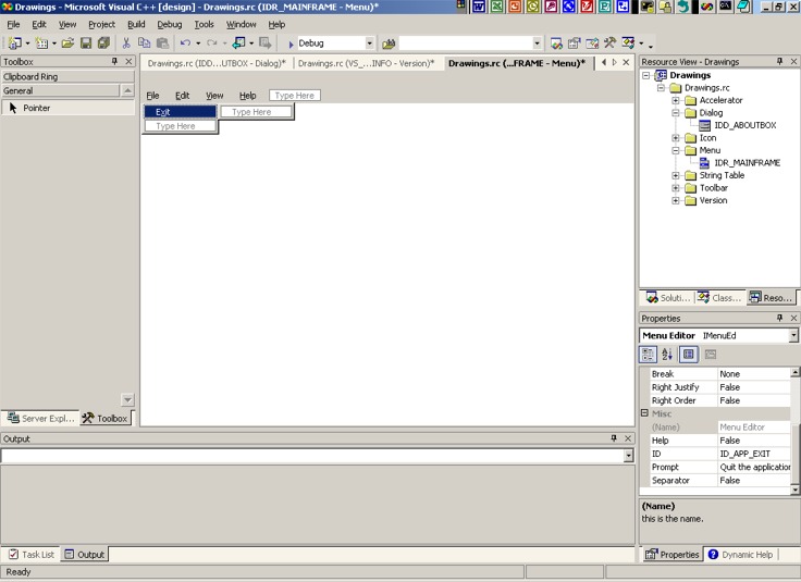
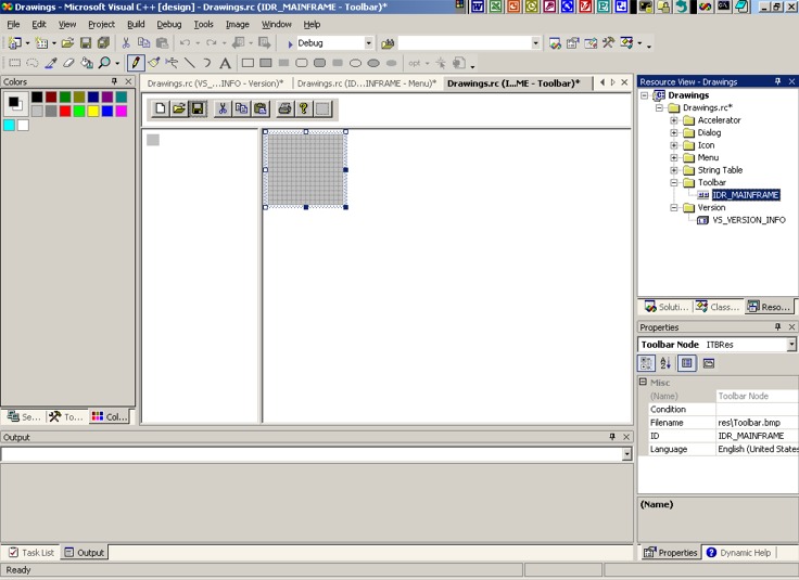
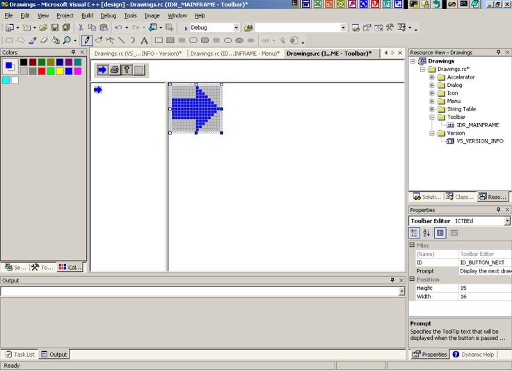
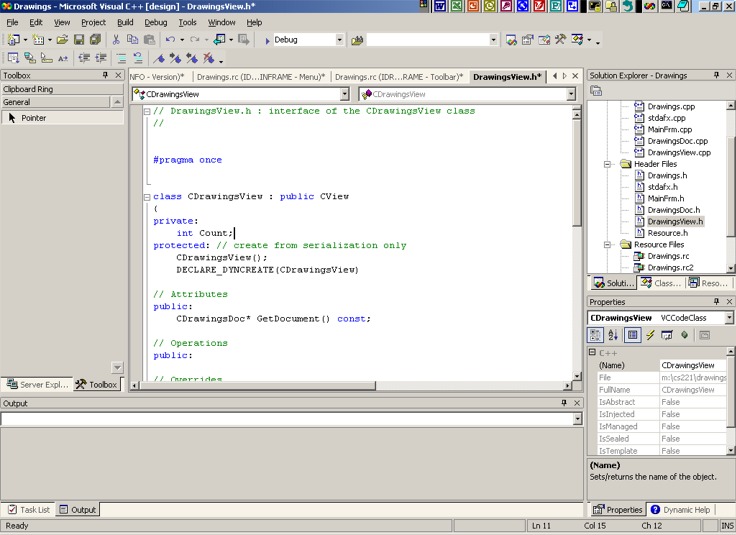
Software Design Using C++Single Document Interface with Visual C++ .NETDrawing Simple Graphics1) OverviewThese directions apply to Visual C++ .NET specifically. The task is to write a Windows app that draws simple graphics. We will use the AppWizard's single document interface. We will place an additional button on the toolbar for the user to click on to add a new drawing on the screen. 2) Using AppWizardWe assume that you have Visual C++ .NET running and have opened an existing solution (used to group several projects together). Begin by making a new project of type "MFC Application". (Use File, New, Project, Visual C++ Projects and then click on MFC Application.) Name the project Drawings and select the Add to Solution option to add this Project to your existing Solution (workspace). Under Application type select Single document. Windows XP users should uncheck Common Control Manifest found under Advanced Features. The default values should be fine for all of the other items. (Note that as discussed under the Dialog-based Interface section, you might want to choose the Statically Linked option instead of the "Shared DLL" option, particularly if you want to use your .exe file under various versions of Windows.) Click on the Finish button. It is useful to have several windows on the screen. Use View, Solution Explorer if the Solution Explorer is not already visible on the screen. Similarly, use View, Class View as well as View, Resource View to get these windows on the screen. Lastly, use View, Properties Windows to make sure that one is also visible. Click on the Resource view tab. If need be, click on the + in front of Drawings and Drawings.rc to expand what you see. Also click on the + in front of "Dialog" in order to expand this folder. Make the Drawings project the currently active one. (You can do this by clicking on the Drawings folder in the Solution Explorer and then using Project, Set as Startup Project. An alternative is to right click on the Drawings folder and select Set as Startup Project from the resulting context-sensitive menu.) 3) Change the About Box and CopyrightIn the Dialog folder in Resource View double click on IDD_ABOUTBOX. Here is a picture of what we have at this point. Then click on the Copyright line. Change the caption to one word: Freeware. (You can do this by changing the caption field in the Properties window.) You can then close the window used for editing the About Box by clicking on the its x close button. In Resource View expand the Version folder and double click on VS_VERSION_INFO. Click on LegalCopyright. You can then change the Value field (found in the Properties window) to Freeware. You can also change any other information fields such as Company Name if you wish. You can examine this picture to see what this screen looks like. Do File, Save All. Close the window used to edit the version information. 4) Changing the MenuExpand the Menu folder in Resource View if necessary. Double click on IDR_MAINFRAME. In the menu editor click on File. We want to delete each item on the File menu except for Exit. Click on each such item and press the Delete key. Even delete the separator bars between menu items, but do not try to delete the blank menu item below Exit. Click on the Edit menu and press Delete in order to remove the entire Edit menu. Leave the View and Help menus alone. Do File, Save All and close the window used to edit the menu bar. 5) Modifying the ToolbarIn Resource View, expand the Toolbar folder if need be. Double click on IDR_MAINFRAME. You should see the standard toolbar. Drag off of the toolbar every button except the print button, the about button (with the question mark on it), and the blank button. Click on this blank button. Then use the drawing tools to draw a blue rightward pointing arrow on the large grid picture of the blank button. (Just click on the blue color and then click on a square in the grid to color that square blue.) This will be your button for displaying the next drawing. While this button is still selected, go to the Properties window and change the ID to ID_BUTTON_NEXT. Also fill in the following as the prompt:
See the lower right portion of this screen shot to see how the above looks in the Properties window. Note that the above changes will allow the user to place the mouse pointer over the button to get information about it. The word Next will be shown near the button when this happens, and "Display the next drawing" will be shown on the status bar at the bottom of the window. You can view the properties of each of the other buttons by clicking on them one at a time. Finally, drag your new blue arrow button to the leftmost position on the toolbar. Do not worry about the fact that there is a new blank button on the toolbar as it will not show up in the completed application. Do File, Save All. Close the window used to edit the toolbar. 6) Add a Message MapNext, we add a message map function to handle things when the user clicks on your new button. We are going to add this one manually. In the Solution Explorer double click on DrawingsView.h to bring up this file in the editor. Find the class declaration and within this the Attributes section. There will already be one entry in the public section of this. Just below this insert the following private variable (field) which we will use to keep track of how many times the new button is clicked.
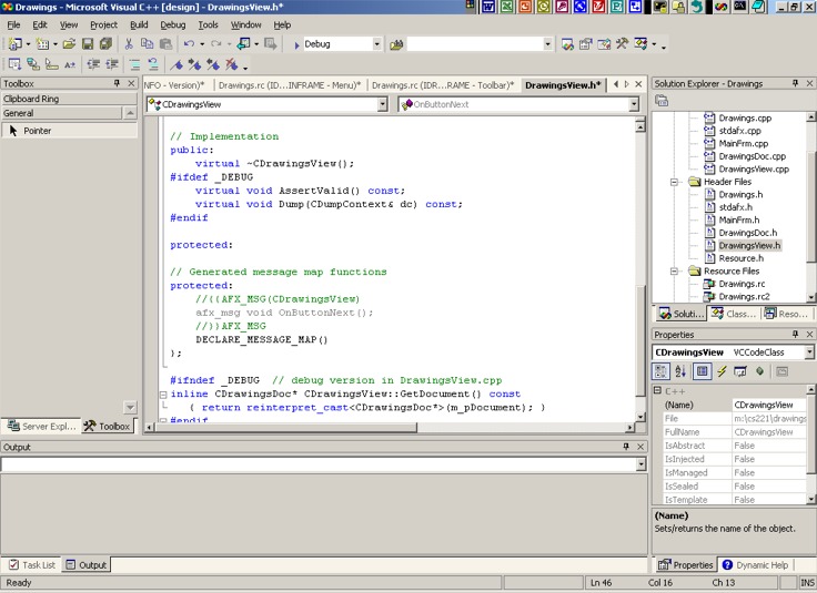
Then find the section labeled "Generated Message Map Functions" and add the following to the protected section, right before the line that says DECLARE_MESSAGE_MAP().
The
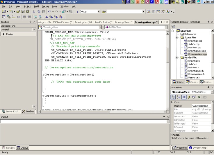
Note how the added lines associate giving the command of clicking on the button whose ID is ID_BUTTON_NEXT with the OnButtonNext function. We still need to add code for this function. Add the following to the end of the same file:
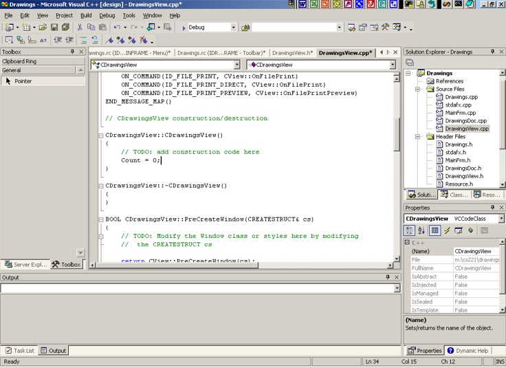
Note that the Count variable is used to keep track of what drawing(s) we are to display. When Count is 0 we will display only the initial drawing. When Count is 1 we will display the first 2 drawings. When Count is 2 we will show the first 3 drawings. When Count is 3 we will display all 4 drawings. Finally, if Count is 4 (or greater), the above code pops up a message box that tells us that there are no more drawings. The InvalidateRect function call above causes the OnDraw function to redisplay the window. We also need to add one line of code to the constructor for CDrawingsView. In the same file, find the constructor and change it to read as follows. This simply initializes the Count variable to zero. Then do File, Save All.
7) Drawing GraphicsFind the outline of the OnDraw function in the DrawingsView.cpp file. Change the code for this function to the following:
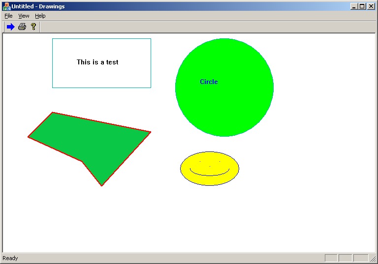
The comments in the code above and the obvious names of many of the functions will give you a good idea of what the code does. Use Help, Search to look up any details that you need on a particular function. (Hint: use "Visual C++" in the "Filtered by:" box so that you don't see matches for Visual Basic, etc.) It would help to know that for drawing on the screen the upper left corner has coordinates (0, 0) and that the x coordinate increases as you go horizontally across the screen to the right, while the y coordinate increases as you go downward on the screen. Do File, Save All. Do Build, Build Drawings and fix any minor errors that are noted. Then run your application by clicking on the ! button on the toolbar. When it first starts you should see a rectangle with the first little drawing in it. Clicking on the right arrow button should then add the second drawing, etc. Compare you results to this picture showing all of the items drawn. 8) For Further Practice (Optional)You might want to modify the above program to draw something of interest to you. You can look up the list of drawing commands by using Help, Search and looking for CDC (the device context class). Double click on the item that says "CDC Members (MFC)". If you know the name of the particular function, such as Ellipse, that you want to look up, you can of course look it up directly. Related Item:Single Document Interface with Visual C++ 6.0 Back to the main page for Software Design Using C++ |
Computing & Information Systems |
|

 Search CIS Site
Tutorials
Search CIS Site
Tutorials
|